Design
Updates to the OpenHIM architecture for RHIE - Nov 2013
The HIM core was split out from the RHIE specific orchestrator and adapters so that the core could be more general. The overall design of this is described here: https://wiki.ohie.org/display/SUB/OpenHIE+Interoperability+Layer+design+document
Each orchestrator and adapter is now a separate mule applications and the OpenHIM core application handles the routing, authentication and logging functions and then delegates to a particular orchestrator or adapter.
RHEA Health Information Mediator Architecture and Design
The RHEA Health Information Mediator (Interoperability Layer) is built as an implementation of the Health Information Mediator architecture. This architecture was researched and designed with the need of the RHEA project in mind. This architecture is described in the paper entitled "An Interoperability Architecture for the Health Information Exchange in Rwanda" authored by Ryan Crichton, Deshendran Moodley, Anban Pillay and Christopher Seebregts. This paper has been submitted for in FHIES 2012 (http://simbioses.ca/FHIES12/) conference proceedings.
The following section is a direct excerpt from the paper. It describes the high level functions and architecture of the RHEA Health Information Mediator. Following this excerpt the details of how the architecture of the HIM is implemented using Mule ESB are given.
HIM Architecture Excerpt:
4 The architecture of the Health Information Mediator
This section describes the design of the Health Information Mediator shown in figure 1. The descriptions provided are based on the ISO 42010 architecture descriptions [13 ,8] .
ISO/IEC FDIS 42010 provides a formal language and a metamodel for creating, analysing and sustaining architecture descriptions. An architecture can be described by a number of architectural viewpoints with each viewpoint framing a number of concerns (including requirements) of different groups of stakeholders with an interest in the system. Together, these views make up the architecture description. Based on the requirements identified in section 3, three major viewpoints and their associated concerns are described below. 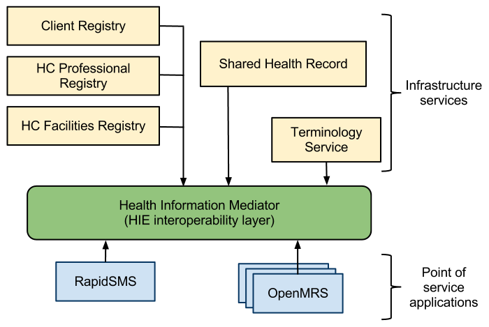
Fig. 1: The architecture of the Rwandan Health Information Exchange
4.1 Logical Viewpoint
This viewpoint describes the overall functionality of the system. The model kinds include custom diagrams showing how transactions flow through the architecture.
This view frames the following concerns:
- The architecture must facilitate interoperability between heterogeneous systems
- The architecture must provide a low barrier to entry to connect both new and legacy systems
- Changes should be kept local and not propagate through the system
Based on the above requirements, we have designed a middleware system, the Health Information Mediator (HIM) to enable interoperability between participating systems and infrastructure services. The HIM is based on the Enterprise Service Bus architectural model.
An Enterprise Service Bus (ESB)[5 ,20] is a middleware system that facilitates interoperability by providing a central bus that manages all communications between systems. Since the components within an ESB are loosely coupled and can run completely independently of each other, each component can still function independently when other components fail.
ESB is a well established architectural model for meeting the requirements associated with interoperability between distributed and disparate systems that has previously been applied to the problem of interoperability between disparate health information systems[19 ,12] .
All participating systems in the HIE are represented as services. Systems that provide services to other systems are termed service providers, while systems that make requests of other systems are termed service requesters. All service requests are made via the HIM. The HIM thus provides mediation and orchestration functions within the system.
Our approach contains three major components described by the following 3-tuple:
HIM = (I, P, M)
where HIM is the Health Information Mediator, I is the Interface component, P is the Persistence component and M is the Mediation component.
Figure 2 shows the order in which transactions flow through each of the components
. 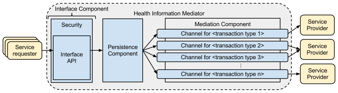
Fig. 2: Overview of components in the HIM architecture
Each of these components are described below:
I - Interface Component
All interactions are carried out via the HIM. The interface component exposes an API that allows systems or applications to make service requests through the HIE. It is responsible for defining and handling all incoming service requests. Service requests are received using a standard protocol (e.g. HTTP) and translated into a common internal format that is accessible by the other components in the layer (e.g. Java Object). The request is then passed to the persistence component for further processing.
This component not only provides a single and consistent entry point for all service requests, but also enforces security and access policies for the HIE.
A single point of access simplifies interactions with the HIE as the systems can make service requests without needing to know the location or security requirements of the service providers.
The API currently uses web services which affords the HIM greater flexibility when connecting systems using varying platforms and technologies. The functions provided by the API are defined according to the requirements of the HIE implementation. In the Rwandan use case this includes functions to save and query a patient’s clinical record within the shared health record and to query and update records in the client, provider and facility registries.
This component also provides a central place for defining and applying advanced security policies. In this component, access to the API and access to specific functions of the API should be strictly controlled. The component also allows data-level security policies to be applied, if needed. In this paper, we have not addressed the complexities of defining how these security policies could be applied.
P - Persistence Component
This component receives authorised service requests from the interface component and starts and monitors a transaction required to fulfill the request to completion.
It stores a copy of each transaction received by the HIM and maintains a persistent data store for the request data, the response data and metadata for each transaction. This data is stored for logging and audit purposes and can also be used to identify and handle exception conditions. This allows the administrators of the system to identify and solve recurring problems or failures. In this paper, we acknowledge that audit trails and exception handling are important issues to consider within a HIE however we do not explore these issues further, at this stage.
The metadata stored around transactions allow administrators of the system to monitor transactions and gauge the health of the system. This is useful for discovering bottlenecks and performance problems.
M - Mediation Component
The mediation component executes transactions. Its main functions are orchestration and message translation.
The mediation component is made up of a number of transaction channels. A channel is provided for each transaction type, e.g. a transaction type to save a patient’s encounter. It contains the necessary logic to normalise, orchestrate and de-normalise that transaction. Each function exposed by the API in the interface component maps to a transaction type and therefore to a transaction channel.
Below we describe the process that occurs within a single transaction channel contained within the mediation component.
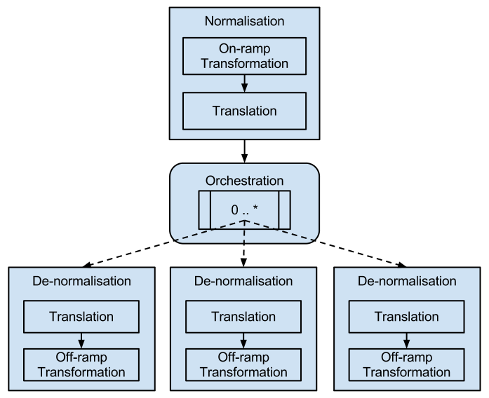
Fig. 3: The workflow of a transaction channel within the transaction mediation component
Figure 3 shows the inner workings of the transaction mediation component described earlier. Each transaction type has its own transaction channel. The diagram represents the workflow within a single transaction channel.
A transaction channel always begins with a normalisation sub-component. This sub-component transforms the request message contained within a transaction to a normalised state. After this process the transaction data must be in a consistent and predictable format to allow components following this to process it in a predictable fashion, no matter what format it arrived in. This process consists of 2 operations. Firstly, an on-ramp transformation is applied. This ensures syntactic interoperability for the transaction. For example, if the transaction arrives from a legacy application that only supported exporting data in a custom XML format, this process would ensure that the XML is transformed into a form that the rest of the exchange can understand, e.g. an HL7v2 1 message. Secondly, a translation operation is invoked. This operation is responsible for ensuring the codes and code systems used within the transaction are translated to a standard set of vocabulary or clinical terms that have a common interpretation by other components of the HIM. This involves a call to the terminology service to translate and verify that the codes used within the transaction are in or are translated to an internal standard vocabulary. The terminology server is responsible for maintaining a standard vocabulary and mappings to other vocabularies used by participating systems. In this way semantic interoperability between service requesters and providers is achieved.
Following this, the transaction is sent to the orchestration sub-component. This sub-component is responsible for performing implementation-specific orchestration for the current transaction. The process of orchestration is described in Peltz et al[18] . The aim of the orchestration component is to execute the received transaction and perform any consequent action(s) required for this transaction. This could include 0 or more calls to external services. This component also compiles the response for the executed transaction and returns this to the persistence component which forwards the response to the service requester via the interface component.
A de-normalisation sub-component is provided for each external service. This sub-component is responsible for transforming (or constructing) a service request into a format that is understandable to the service provider. This operates in a similar way to the normalisation component except the operations occur in reverse order. This approach serves to decouple service providers from the orchestration component, which allows for service providers to be easily modified or replaced with minimal impact on the mediation component.
4.2 Scalability view
This view serves to show how the architecture can scale.
This viewpoint frames the following concern:
- The architecture must scale in terms of the number and volume of transactions
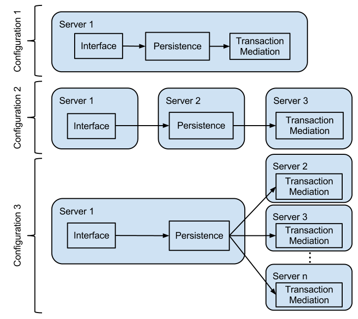
Fig. 4: Scalability configurations of the HIM architecture
Figure 4 show the scalability of the architecture. In the architecture there are 3 major components; the interface API, the persistence component and the mediation component. Each of these components are loosely coupled to allow them to be deployed accross different servers. This is shown in ‘Configuration 2’ in figure 4. The 3 components are responsible for separate units of work. This loose coupling allows the components to be spread over different hardware as long as they can communicate over a network. The ESB architectural model used for this architecture ensures that the components are loosely coupled and can be deployed distributedly.
It is also feasible to further separate the persistence component and the transaction mediation component through clustering. The persistence component performs the static function of persisting any transaction that passes through it. As this function is not dynamic it could easily be replicated over multiple servers with the provision that the data store is kept in sync. This component could also be invoked in an asynchronous fashion as the mediation component subsequent to it does not require this process to complete in order to continue.
The transaction mediation component can be scaled horizontally. The transaction mediation component holds a set of channels, one for each transaction type that is supported by the implementation. Each of these channels encapsulates information about how each transaction should be transformed and orchestrated. Each transaction channel runs independently which allows for deployment of the channels across different servers. This is shown in configuration 3 in figure 4.
4.3 Adaptability view
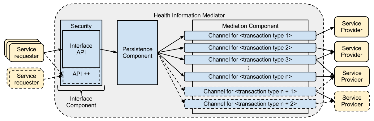
Fig. 5: Adapability of the HIM architecture
This view shows the architecture’s ability to grow with a country’s NHIS and how new services can be easily added or changed within the architecture.
This view frames the following concern:
- The architecture must be adaptable in a changing environment
Adaptability is an important consideration for this architecture. Figure 5 shows how additional services could be added to the architecture. As can be seen, to add additional services the interface component’s API needs to be extended to add new API endpoints for each new function that needs to be supported. The persistence component is generic enough that it does not require any change to process new types of service requests. The transaction mediation component is where most of the changes are required. This component is designed to encapsulate transaction mediation logic for each transaction type. A new transaction channel can easily be added to support a new type of service request. The channel will encapsulate all the logic for normalising the transaction, executing the necessary orchestration steps and to de-normalise the transaction when an external service orchestration call is made. This encapsulation simplifies the addition of new service request types as functionality increases and the HIE expands.
Mule ESB Implementation
The HIM architecture for RHEA is implemented using Mule ESB. This gives us the platform to implement the features needed for RHEA. The following sections describe how each of the components are implemented using Mule.
Interface Component
The interface component is implemented in a single mule flow called interface.mflow. We chose to use RESTful web service for the messaging aspect of the RHEA HIM, so, this component exposes a rest API.
Persistence Component
The interface component is implemented in a single mule flow called persistence.mflow.
Mediation Component
The mediation component has a number of parts to it. The first being the transaction router. This is implemened in the mule flow entitled transactionrouter.mflow in the mediation folder.
Within the mediation folder there are a number of other folders. Each of these folders represents a transaction channel. Within each of these transaction channel are a number of .mflow files that together can process and orchestrate the transaction. Specifically the following flows are required:
- xxxxx-normalization-generic.mfow - To normalize the transaction by providing an on-ramp transformation and a translation transformation.
- xxxxx-orchestration.mflow - To perform the orchestration for this transaction. This can call 0 or more de-normalization flows to call additional services.
- xxxxx-denormalization.mflow - To prepare the current transaction for delivery to a different service as required by the orchestration for this transaction (These could be 0 or more of these flows).
RestfulHttp Objects
For ease of use each restful requests is converted into a RestfulHttpRequest object and when an orchestration needs to return a response a corresponding RestfulHttpResponse object should be created and returned. This provides easy access to the important information of the rest request and response.